In a previous blog we demonstrated the bits and pieces of wood that make up the speeder sweep castings. Once we have the bits and pieces all brad-nailed and glued together, we create fillets (curves) between the ribs and the deck using automotive car body putty. It's a simple matter of squeezing the putty out of the tube and wiping it on the wood, smoothing it out with our finger to create a nice curve. A rubber glove helps to keep the putty off of our fingers. Several coats of body putty, with light sandings in between coats, and soon have nice curved fillets.
The foundryman is not a pattern maker so he needs to know what part of the pattern is the final casting and what part is sand core. In order to help him out, we give the patterns several coats of black and yellow paint - black outlining the final casting and yellow outlining the sand cores. In this way, when he pulls the pattern out of the mold, he knows which sand core goes into which cavity. The yellow outline of the pattern corresponds to a specific sand core.
Here's the top view of our pattern.
A head-on view. In addition to seeing the profile of the two sand cores that we'll be using, you can readily see that our pattern is in two parts.
You can also see where our parting line will be between the drag and the cope of our flask. What may not be readily evident is a potential undercut on the left side of the photo. When we put the top half of the pattern onto the base, we'll have to get rid of that undercut by building the drag part of our sand mold up before we fit the cope onto the drag.
A side view. Again you can see the top half of the pattern and the bottom half when you look at the wing.
Another side view but with the pattern rotated 180 degrees. You can readily see that our pattern is in two parts.
And a bottom view with the top part of the wing detached from the base. This photo clearly shows the ribs of our casting.
Here's an end view with the two sand cores that will fit into the mold cavity created by the yellow parts of the pattern. Note how the outline of the sand cores corresponds to the yellow outline of the pattern.
Our next step is to make sure that we can make a mold that will accept the sand cores and be ready for the molten aluminum. In effect, this will be a trial run of our mold making to make sure that everything fits together (we hope!).
Monday, September 6, 2010
Thursday, August 26, 2010
A Morning At Alumaloy Castings (1990) Limited - How To Make A "Negative" Casting
The Company - Alumaloy Castings (1990) Limited, 424 Birchmound Rd, Toronto, ON, Canada, M1K 7M6
The Challenge - Using a "patio stone" rock as a pattern, make a "negative" of the rock. Then use that "negative" pattern to make a mold to make an aluminum casting. The aluminum casting will then be used by the landscape customer to make concrete "patio stone" rocks.
The Craftsmen - Marco and Paul, two of the principals of Alumaloy and their employees.
The Circumstances - A landscape customer wants to make concrete "patio stone" rocks out of a slurry mix of concrete. They sculped the "patio stone" pattern out of the slurry mix. They now need to make a "negative" mold out of this "patio stone" in order to to produce dozens of stones that are similar in shape, size, and look. Using the "patio stone" master for their pattern, they tried making the negative out of plaster of Paris without success. The landscape customer has now come to Alumaloy for a solution. And I've been fortunate to have just arrived on the scene with a challenge of my own (a much smaller one) to offer Alumaloy - but that's another story for another day.
Making The "Negative" Pattern
In a previous blog, I've discussed using sodium silicate and silica sand to make sand cores. Alumaloy uses the stuff to make their one-of-a-kind sand cores all the time. There's always a barrel or two of the stuff mixed up and ready to use at a moment's notice.
Paul put the patio stone face down on a mold board inside the cope-half of a flask that had lots of draft on the sides. He then stuffed some mixed sand along the edges to get rid of the undercuts (there were a few on the back of the stone) and oversprayed the mixed sand with some brown lacquer. This would help him to identify where the edges of the stone were. He added some 1/8" steel rod as reinforcing steel and some hooks so that they could lift the negative pattern out of the green sand mold. He also drilled some holes into the sides of the flask to insert some steel rods to tap the patio stone when it came time to remove the stone from the sand mix.
He filled the flask with the sodium-silicate-and-sand mix, tamping the sand tightly around the patio stone. When the flask was full, he struck off the excess sand. Next, he made about a dozen holes in the sand using a 1/8" steel rod. These holes would be used to get carbon dioxide (CO2) into the sand mix. The CO2 would create a chemical reaction with the sand mix to harden the sand into a solid block of sand.
I wouldn't have believed it if I hadn't seen it with my own eyes! Using an air hose attached to the cylinder of CO2, he gave each hole a two-second (it could have been a 4 or 5 second) shot of CO2. He repeated this again. In less than 5 minutes, he had a solid chunk of sand which had the exact pattern (ridges, indentations, grain, etc) of the face of the patio stone.
Problem was he now had a 150 lb block of sand that he had to turn over to remove the original patio stone pattern from the block of sand. Calling on Marco (who was always on hand offering advice and going for things to keep things moving along), they both managed to turn the flask and block over so that the patio stone was exposed. A bit of digging and jabbing here and there and the patio stone came out. They next sprayed the sand casting with lacquer to seal the block of sand. As seen in the photo below, they now had the "negative" pattern that they needed to make the green sand mold and an aluminum casting. You can clearly see the fine detail of the rock that has been impressed into the "negative" sand pattern.
Placing the negative pattern on a pallet truck, they wheeled the 150 lb pattern into the mold-making part of the shop, lifted the heavy pattern face-up onto a mold board and then placed the drag-half of a large 30"x 36" flask over the pattern. This provided just enough clearance around all sides of the pattern.
Marco then gave the pattern a good dusting with talc parting powder to make sure the pattern would easily release from the green sand when the pattern was lifted out of the drag-half of the mold. He next riddled a fine layer of green sand over all of the pattern, ramming the sand with his fists as he covered the pattern. If he had used an air-ram at this point, he would have cracked the pattern.
He continued layering in green sand, making sure it was rammed tightly into the drag. At this stage, he started to use the air-ram to make sure the drag was well packed.
When the drag was full, he struck off the excess green sand and called on Paul and another worker to turn the drag over. The whole affair - pattern, sand, drag and mold board - weighed about 400 pounds.
With the drag and pattern now face-up, he gave the pattern and the top of the drag-surface of the mold a good dusting of talc parting powder to make sure the cope-half of the flask would readily lift off of the drag-half.
He next placed the cope-half of the flask on top of the drag and riddled a layer of green sand on top of the pattern. Again, using his fists so as not to crack the pattern, he rammed the green sand all around the pattern.
He next set some wedge-shaped chunks of steel on top of the pattern to create risers. As explained in a previous blog, the risers allow the molten aluminum to come up into the voids created by the wedges and allows the gases to escape as the aluminum cools. If the voids created by the risers are large enough, the voids also serve as a reservoirs of molten aluminum that keep the mold filled as the aluminum cools and shrinks.
He also added a sprue cutter to form a sprue that would be used to pour molten aluminum into the mold.
In order to create a sufficiently large reservoir of molten aluminum, he removed the chunks of steel used to create the risers and replaced them with large ceramic-like cylinders (the material is similar to that found in some professional back-yard foundries and kilns). He continued to add and ram more sand until the top of the cope was full. He next struck off any excess green sand and used a tamper to smooth the top of the surface.
Marco and another worker then lifted the cope off the drag while Paul rolled the drag out of the way. The cope alone weighed more than 200 lbs so it was strictly a "lift the cope", "roll the drag out of the way" (thank god for those rollers, eh!), and "set the cope on its side". A minimum amount of moves in a minimum amount of time. Any miscalculations and the cope would have ended up on the floor as a big pile of green sand.
They next lifted that 150 lb pattern out of the drag. It was definitely not an easy job as it took three of them to do it. Here's what the drag-half of the mold looks like. You can see the pattern in the mold that carries all of the fine detail of the original "patio stone" rock.
But first Paul and Marco worked on the cope-half of the pattern cleaning and blowing off the loose sand and fixing any imperfections that might have been on the cope-half of the pattern. After cleaning out the holes for the sprue and risers, they cut gates into the mold so that the molten aluminum would flow evenly and continuously into the mold.
Marco and Paul next turned their attention to the drag-half of the pattern, blowing off the loose sand and cleaning up any imperfections. They had to cut into the sides of the green-sand mold to remove the pattern but these were easily fixed up with handfuls of green sand and smoothing with a trowel.
They next placed the cope back on top of the drag. They clamped the four corners of the flask so that the cope wouldn't "float" off the drag when the molten aluminum was poured into the mold. The mold was now complete and ready for the aluminum pour.
The key thing in an aluminum (or any) pour is to keep a steady "flow" of molten aluminum pouring into the mold - particularly with a mold this large. It took two "pots" and 6 "ladles" of molten aluminum to fill the mold and to leave a good supply of molten aluminum in the risers.
Marco then "babysat" the mold for the next 45 minutes periodically pouring a ladle or two of molten aluminum into the top of the riser tubes as the aluminum in the mold cooled, drawing down the reservoir of molten aluminum in the riser tubes.
After a couple of hours, the casting had cooled sufficiently to knock it out of the green sand mold.
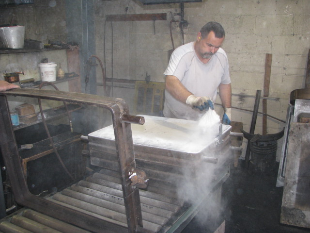
The flask was upended and the casting pulled out of the green sand. The green sand was steaming hot. Don't touch! It will badly burn your fingers to a crisp before you can say "Ouch!!".
Next, the sprues and risers (now solid) were cut off and any sharp edges on the sides of the casting ground down.
The casting was next transported over to the weigh scales and weighed.
110 pounds of solid aluminum, ready to receive the concrete slurry to make "patio stone" rocks.
A job well done! And I had a first-hand look at how aluminum castings are made.
The Challenge - Using a "patio stone" rock as a pattern, make a "negative" of the rock. Then use that "negative" pattern to make a mold to make an aluminum casting. The aluminum casting will then be used by the landscape customer to make concrete "patio stone" rocks.
The Craftsmen - Marco and Paul, two of the principals of Alumaloy and their employees.
The Circumstances - A landscape customer wants to make concrete "patio stone" rocks out of a slurry mix of concrete. They sculped the "patio stone" pattern out of the slurry mix. They now need to make a "negative" mold out of this "patio stone" in order to to produce dozens of stones that are similar in shape, size, and look. Using the "patio stone" master for their pattern, they tried making the negative out of plaster of Paris without success. The landscape customer has now come to Alumaloy for a solution. And I've been fortunate to have just arrived on the scene with a challenge of my own (a much smaller one) to offer Alumaloy - but that's another story for another day.
Making The "Negative" Pattern
In a previous blog, I've discussed using sodium silicate and silica sand to make sand cores. Alumaloy uses the stuff to make their one-of-a-kind sand cores all the time. There's always a barrel or two of the stuff mixed up and ready to use at a moment's notice.
Paul put the patio stone face down on a mold board inside the cope-half of a flask that had lots of draft on the sides. He then stuffed some mixed sand along the edges to get rid of the undercuts (there were a few on the back of the stone) and oversprayed the mixed sand with some brown lacquer. This would help him to identify where the edges of the stone were. He added some 1/8" steel rod as reinforcing steel and some hooks so that they could lift the negative pattern out of the green sand mold. He also drilled some holes into the sides of the flask to insert some steel rods to tap the patio stone when it came time to remove the stone from the sand mix.
He filled the flask with the sodium-silicate-and-sand mix, tamping the sand tightly around the patio stone. When the flask was full, he struck off the excess sand. Next, he made about a dozen holes in the sand using a 1/8" steel rod. These holes would be used to get carbon dioxide (CO2) into the sand mix. The CO2 would create a chemical reaction with the sand mix to harden the sand into a solid block of sand.
I wouldn't have believed it if I hadn't seen it with my own eyes! Using an air hose attached to the cylinder of CO2, he gave each hole a two-second (it could have been a 4 or 5 second) shot of CO2. He repeated this again. In less than 5 minutes, he had a solid chunk of sand which had the exact pattern (ridges, indentations, grain, etc) of the face of the patio stone.
Problem was he now had a 150 lb block of sand that he had to turn over to remove the original patio stone pattern from the block of sand. Calling on Marco (who was always on hand offering advice and going for things to keep things moving along), they both managed to turn the flask and block over so that the patio stone was exposed. A bit of digging and jabbing here and there and the patio stone came out. They next sprayed the sand casting with lacquer to seal the block of sand. As seen in the photo below, they now had the "negative" pattern that they needed to make the green sand mold and an aluminum casting. You can clearly see the fine detail of the rock that has been impressed into the "negative" sand pattern.
Placing the negative pattern on a pallet truck, they wheeled the 150 lb pattern into the mold-making part of the shop, lifted the heavy pattern face-up onto a mold board and then placed the drag-half of a large 30"x 36" flask over the pattern. This provided just enough clearance around all sides of the pattern.
Marco then gave the pattern a good dusting with talc parting powder to make sure the pattern would easily release from the green sand when the pattern was lifted out of the drag-half of the mold. He next riddled a fine layer of green sand over all of the pattern, ramming the sand with his fists as he covered the pattern. If he had used an air-ram at this point, he would have cracked the pattern.
He continued layering in green sand, making sure it was rammed tightly into the drag. At this stage, he started to use the air-ram to make sure the drag was well packed.
When the drag was full, he struck off the excess green sand and called on Paul and another worker to turn the drag over. The whole affair - pattern, sand, drag and mold board - weighed about 400 pounds.
With the drag and pattern now face-up, he gave the pattern and the top of the drag-surface of the mold a good dusting of talc parting powder to make sure the cope-half of the flask would readily lift off of the drag-half.
He next placed the cope-half of the flask on top of the drag and riddled a layer of green sand on top of the pattern. Again, using his fists so as not to crack the pattern, he rammed the green sand all around the pattern.
He next set some wedge-shaped chunks of steel on top of the pattern to create risers. As explained in a previous blog, the risers allow the molten aluminum to come up into the voids created by the wedges and allows the gases to escape as the aluminum cools. If the voids created by the risers are large enough, the voids also serve as a reservoirs of molten aluminum that keep the mold filled as the aluminum cools and shrinks.
He also added a sprue cutter to form a sprue that would be used to pour molten aluminum into the mold.
In order to create a sufficiently large reservoir of molten aluminum, he removed the chunks of steel used to create the risers and replaced them with large ceramic-like cylinders (the material is similar to that found in some professional back-yard foundries and kilns). He continued to add and ram more sand until the top of the cope was full. He next struck off any excess green sand and used a tamper to smooth the top of the surface.
Marco and another worker then lifted the cope off the drag while Paul rolled the drag out of the way. The cope alone weighed more than 200 lbs so it was strictly a "lift the cope", "roll the drag out of the way" (thank god for those rollers, eh!), and "set the cope on its side". A minimum amount of moves in a minimum amount of time. Any miscalculations and the cope would have ended up on the floor as a big pile of green sand.
They next lifted that 150 lb pattern out of the drag. It was definitely not an easy job as it took three of them to do it. Here's what the drag-half of the mold looks like. You can see the pattern in the mold that carries all of the fine detail of the original "patio stone" rock.
But first Paul and Marco worked on the cope-half of the pattern cleaning and blowing off the loose sand and fixing any imperfections that might have been on the cope-half of the pattern. After cleaning out the holes for the sprue and risers, they cut gates into the mold so that the molten aluminum would flow evenly and continuously into the mold.
Marco and Paul next turned their attention to the drag-half of the pattern, blowing off the loose sand and cleaning up any imperfections. They had to cut into the sides of the green-sand mold to remove the pattern but these were easily fixed up with handfuls of green sand and smoothing with a trowel.
They next placed the cope back on top of the drag. They clamped the four corners of the flask so that the cope wouldn't "float" off the drag when the molten aluminum was poured into the mold. The mold was now complete and ready for the aluminum pour.
The key thing in an aluminum (or any) pour is to keep a steady "flow" of molten aluminum pouring into the mold - particularly with a mold this large. It took two "pots" and 6 "ladles" of molten aluminum to fill the mold and to leave a good supply of molten aluminum in the risers.
Marco then "babysat" the mold for the next 45 minutes periodically pouring a ladle or two of molten aluminum into the top of the riser tubes as the aluminum in the mold cooled, drawing down the reservoir of molten aluminum in the riser tubes.
After a couple of hours, the casting had cooled sufficiently to knock it out of the green sand mold.
The flask was upended and the casting pulled out of the green sand. The green sand was steaming hot. Don't touch! It will badly burn your fingers to a crisp before you can say "Ouch!!".
After letting the casting cool overnight, it was moved over to the clean-up part of the shop where Paul wire-brushed the remaining green sand off the casting. 
Once the green sand had been brushed off, you could clearly see the detail of the rock in the aluminum casting. The sodium silicate and silica sand had clearly captured the detail of the "patio stone" rock. 
Next, the sprues and risers (now solid) were cut off and any sharp edges on the sides of the casting ground down.
The casting was next transported over to the weigh scales and weighed.
110 pounds of solid aluminum, ready to receive the concrete slurry to make "patio stone" rocks.
A job well done! And I had a first-hand look at how aluminum castings are made.
Monday, May 3, 2010
Sand Cores Using Sodium Silicate and Carbon Dioxide (CO2)
Sand, when mixed with the correct ratio of sodium silicate, rammed into a core box, and then exposed to carbon dioxide (CO2), will result in a very hard and durable sand core. Never having used sodium silicate (and never having made sand cores before!), this was an excellent lesson in learning what works and what doesn't.
PQ Corporation is the largest manufacturer of sodium silicates, one of the most widely used chemicals in the world. Their brochure on sodium silicate has this table which describes the various strengths of sodium silicate available.
N-Grade Sodium Silicate
The key measure of sodium silicate is the weight ratio of its two major components - Silica DiOxide (SiO2)to Sodium Oxide (Na2O) (the column titled "Wt. Ratio SIO2 / NA2O"). The most commonly available sodium silicate has a weight ratio of 3.22 parts of Silica DiOxide to 1 part of Sodium Oxide with a solids content (active ingredients) of 37.6% (8.90+28.7=37.6 from Table 2 above). The rest (62.4%) is water. This is sold as "N" grade sodium silicate and is NOT the best choice for making sand cores as it doesn't provide very good strength to the sand core. The sand core will slowly disintegrate when handled. This type of sodium silicate has the viscosity of a cheap liquid dishwashing soap. Table 2 above describes it as a syrupy liquid.
I made the mistake of using the 3.22 N-grade sodium silicate (it may even have been a weaker solution) with very poor results. Even after 24 hours and constant exposure to CO2, the sand cores wouldn't hold together. For those that did stick together, I would end up with loose sand grains in my hand whenever I handled them.
RU-Grade Sodium Silicate
The best type of sodium silicate for making sand cores has a weight ratio of 2.40 parts of Silica DiOxide to 1 part of Sodium Oxide with a solids content (active ingredients) of 47.05% (13.85+33.2=47.05 from Table 2 above) - a 25% increase in active ingredients over the N-Grade stuff!! This is typically sold as "RU" grade sodium silicate and has the viscosity of concentrated liquid laundry detergent - it pours very slowly. Table 2 describes it as a heavy syrup.
I got some 2.4 RU-grade sodium silicate from CM and today mixed up a batch of sand to make some sand cores.
Mixing The Sand And Sodium Silicate
I first got all of my supplies, cups, bags, and stir sticks together and laid them all out on a sheet of plastic to make the cleanup easier. (The McDonald's cup is my supply of sand - easier to pour from a small cup than from a 25 kg bag, eh!?) I then put a smaller sheet of plastic down on top of the larger sheet so that I could easily recover any spilled sand.
To make the sand cores, I first filled the core box with dry 90m silica sand and poured it into a Ziploc bag. I added about 10% more dry sand as it will compact more when the sodium silicate is added to the mix.
Using my Canadian Tire "Star-Frit" scale, I weighed the baggie at 376 grams.
I put an empty plastic cup (clean and dry!) on the scale and zeroed it out.
I next decanted 38 grams (10%) of 2.4 RU-grade sodium silicate from my large supply bottle into the cup.
I poured the liquid into the bag of sand and rolled the sand, sodium silicate, and bag between my hands until the sand and sodium silicate were well and uniformly mixed. The mixture felt only slightly damp but would clump together when squeezed.
Stuffing The Core Box
To make sure the CO2 would penetrate the sand core, I placed 1/4" steel rods into the middle of the core box so that I would have holes through the middle of the sand core. I spooned a small amount of sand mix into the core box and rammed the sand mix around the sides of the box and the steel rod.
More sand mix, more ramming until the core box was filled to the top. I struck the sand mix level with the top of the core box and lightly patted the sand mix so that it was firmly compacted across the top. With a twist, I removed the steel rods from the middle of the sand core leaving nice 1/4" holes through the middle of the sand core.
Using The CO2 Gas
I wouldn't have believed it if I hadn't seen it in person but.... it only takes a few seconds of CO2 gas to turn the loose sand into a hard sand block!! The secret is in how the CO2 is applied to the sodium-silicate-sand mix.
On the right-side of the photo above, you can see a block of wood with a couple of holes in it. And, in the photo below, you can see a plastic container with a hole in the top. Using my blow gun attached to the CO2 cylinder, and pressing down on the top of the plastic container, I slowly gave a 2-second shot of CO2 into the container. This immediately hardened the surface of the sand core.
Removing the plastic container, I then placed the wooden block on the top of the core box, aligning the hole in the wooden block with the hole(s) in the sand core. I slowly gave each hole a 2-second shot of CO2.
I then undid the screws of the core box. Voila, the sand core easily separated from the sides of the wooden core box. In less than 20 seconds from the time of applying the CO2 to starting to undo the screws, I had a solid sand core! Whoodathunkit, eh!!??
I then repeated the CO2 process for my second sand core. The solidified sand core easily slid from the core box.
Ratio of Sodium Silicate To Sand (By Weight!!) Is Very Important!!
The whole secret in using sodium silicate is in the sand mix and the application of the CO2.
In my first try at using sodium silicate, I was short about 3 tablespoons of sand mix. I hastily mixed up a small batch that had about 30% sodium silicate. Bad news!! It wouldn't hold its strength even when repeatedly exposed to the CO2. The sand core was still as soft as when I had rammed it into the core box. I presume the extra liquid prevented the CO2 from penetrating the sand core. So, whether you use a 6% ratio or a 10% ratio, the relative ratio (by weight) of sodium silicate to sand is very important. It doesn't take a lot of sodium silicate.
How You Apply The CO2 Is Very Important!!
While CO2 is heavier than air, my first attempts at using sodium silicate weren't that good. I placed the wet sand cores into a plastic bag and applied the CO2. On my trip to Alumaloy Castings, I saw how they applied the CO2 to the sand - a small cup-like device attached to their CO2 hose, and a piece of wood with a hole in it held on top of the sand core and aligned with the holes in the sand core. A couple of 2-3 second shots of CO2 and the sand core was as solid as a rock.
It was obvious I needed to apply the CO2 in a more "aggressive" fashion. So I modified my process using a 1-litre plastic container with a hole drilled in the top. I was then able to drive the CO2 right into the exposed surfaces of the sand cores.
To get the CO2 into the holes created by the 1/4" steel rods, I simply drilled a couple of holes into a piece of 1/4" plywood so that I could drive the CO2 right through the middle of the sand cores.
Bigger sand cores? Simply use a bigger plastic container. These sand cores were almost instantly as hard as a brick with very smooth surfaces and sharp edges.
In any event, I'm very pleased with the results. Now we go into full-scale production with the sand cores using sodium silicate and CO2.
PQ Corporation is the largest manufacturer of sodium silicates, one of the most widely used chemicals in the world. Their brochure on sodium silicate has this table which describes the various strengths of sodium silicate available.
N-Grade Sodium Silicate
The key measure of sodium silicate is the weight ratio of its two major components - Silica DiOxide (SiO2)to Sodium Oxide (Na2O) (the column titled "Wt. Ratio SIO2 / NA2O"). The most commonly available sodium silicate has a weight ratio of 3.22 parts of Silica DiOxide to 1 part of Sodium Oxide with a solids content (active ingredients) of 37.6% (8.90+28.7=37.6 from Table 2 above). The rest (62.4%) is water. This is sold as "N" grade sodium silicate and is NOT the best choice for making sand cores as it doesn't provide very good strength to the sand core. The sand core will slowly disintegrate when handled. This type of sodium silicate has the viscosity of a cheap liquid dishwashing soap. Table 2 above describes it as a syrupy liquid.
I made the mistake of using the 3.22 N-grade sodium silicate (it may even have been a weaker solution) with very poor results. Even after 24 hours and constant exposure to CO2, the sand cores wouldn't hold together. For those that did stick together, I would end up with loose sand grains in my hand whenever I handled them.
RU-Grade Sodium Silicate
The best type of sodium silicate for making sand cores has a weight ratio of 2.40 parts of Silica DiOxide to 1 part of Sodium Oxide with a solids content (active ingredients) of 47.05% (13.85+33.2=47.05 from Table 2 above) - a 25% increase in active ingredients over the N-Grade stuff!! This is typically sold as "RU" grade sodium silicate and has the viscosity of concentrated liquid laundry detergent - it pours very slowly. Table 2 describes it as a heavy syrup.
I got some 2.4 RU-grade sodium silicate from CM and today mixed up a batch of sand to make some sand cores.
Mixing The Sand And Sodium Silicate
I first got all of my supplies, cups, bags, and stir sticks together and laid them all out on a sheet of plastic to make the cleanup easier. (The McDonald's cup is my supply of sand - easier to pour from a small cup than from a 25 kg bag, eh!?) I then put a smaller sheet of plastic down on top of the larger sheet so that I could easily recover any spilled sand.
To make the sand cores, I first filled the core box with dry 90m silica sand and poured it into a Ziploc bag. I added about 10% more dry sand as it will compact more when the sodium silicate is added to the mix.
Using my Canadian Tire "Star-Frit" scale, I weighed the baggie at 376 grams.
I put an empty plastic cup (clean and dry!) on the scale and zeroed it out.
I next decanted 38 grams (10%) of 2.4 RU-grade sodium silicate from my large supply bottle into the cup.
I poured the liquid into the bag of sand and rolled the sand, sodium silicate, and bag between my hands until the sand and sodium silicate were well and uniformly mixed. The mixture felt only slightly damp but would clump together when squeezed.
Stuffing The Core Box
To make sure the CO2 would penetrate the sand core, I placed 1/4" steel rods into the middle of the core box so that I would have holes through the middle of the sand core. I spooned a small amount of sand mix into the core box and rammed the sand mix around the sides of the box and the steel rod.
More sand mix, more ramming until the core box was filled to the top. I struck the sand mix level with the top of the core box and lightly patted the sand mix so that it was firmly compacted across the top. With a twist, I removed the steel rods from the middle of the sand core leaving nice 1/4" holes through the middle of the sand core.
Using The CO2 Gas
I wouldn't have believed it if I hadn't seen it in person but.... it only takes a few seconds of CO2 gas to turn the loose sand into a hard sand block!! The secret is in how the CO2 is applied to the sodium-silicate-sand mix.
On the right-side of the photo above, you can see a block of wood with a couple of holes in it. And, in the photo below, you can see a plastic container with a hole in the top. Using my blow gun attached to the CO2 cylinder, and pressing down on the top of the plastic container, I slowly gave a 2-second shot of CO2 into the container. This immediately hardened the surface of the sand core.
Removing the plastic container, I then placed the wooden block on the top of the core box, aligning the hole in the wooden block with the hole(s) in the sand core. I slowly gave each hole a 2-second shot of CO2.
I then undid the screws of the core box. Voila, the sand core easily separated from the sides of the wooden core box. In less than 20 seconds from the time of applying the CO2 to starting to undo the screws, I had a solid sand core! Whoodathunkit, eh!!??
I then repeated the CO2 process for my second sand core. The solidified sand core easily slid from the core box.
Ratio of Sodium Silicate To Sand (By Weight!!) Is Very Important!!
The whole secret in using sodium silicate is in the sand mix and the application of the CO2.
In my first try at using sodium silicate, I was short about 3 tablespoons of sand mix. I hastily mixed up a small batch that had about 30% sodium silicate. Bad news!! It wouldn't hold its strength even when repeatedly exposed to the CO2. The sand core was still as soft as when I had rammed it into the core box. I presume the extra liquid prevented the CO2 from penetrating the sand core. So, whether you use a 6% ratio or a 10% ratio, the relative ratio (by weight) of sodium silicate to sand is very important. It doesn't take a lot of sodium silicate.
How You Apply The CO2 Is Very Important!!
While CO2 is heavier than air, my first attempts at using sodium silicate weren't that good. I placed the wet sand cores into a plastic bag and applied the CO2. On my trip to Alumaloy Castings, I saw how they applied the CO2 to the sand - a small cup-like device attached to their CO2 hose, and a piece of wood with a hole in it held on top of the sand core and aligned with the holes in the sand core. A couple of 2-3 second shots of CO2 and the sand core was as solid as a rock.
It was obvious I needed to apply the CO2 in a more "aggressive" fashion. So I modified my process using a 1-litre plastic container with a hole drilled in the top. I was then able to drive the CO2 right into the exposed surfaces of the sand cores.
To get the CO2 into the holes created by the 1/4" steel rods, I simply drilled a couple of holes into a piece of 1/4" plywood so that I could drive the CO2 right through the middle of the sand cores.
Bigger sand cores? Simply use a bigger plastic container. These sand cores were almost instantly as hard as a brick with very smooth surfaces and sharp edges.
In any event, I'm very pleased with the results. Now we go into full-scale production with the sand cores using sodium silicate and CO2.
Wednesday, April 14, 2010
Patterns Finished!!
Got the patterns finished today. The original casting on the right and one of the patterns on the left. The extra blocks of wood on each side of the wings and the two protrusions on the top are for the sand cores.
Top view
Bottom view. The blocks on each side are core prints. These create voids in the mold that will hold the sand cores. This allows us to draw the pattern out of the sand without destroying the mold. The pink in the middle is body putty that we used to create fillets between the ribs and the base plate.
The wing patterns. There's an extra piece of plywood on the side of each wing. This helps us to line the pattern with the base plate. Once we have holes drilled for our alignment dowels, these pieces will come off.
Drilling holes for the dowel pins to keep the top half aligned with the bottom half. You can see that extra piece of plywood that we use for aligning the wing with the base plate on the left side of the wing. This piece will be removed once we have the holes for the dowel pins drilled.
Once we have the alignment holes drilled, we glue 1/4" wooden dowels in the holes in the wing part of the pattern so that they protrude about 3/8". You can see them sticking out on the left side of the photo below. We next cut the dowels protruding on the top part (right side) of the wing pattern, then sand them so that they are flush with the top surface of the pattern.
Details of how we did it in the next couple of installments. Core boxes to be done next.
Top view
Bottom view. The blocks on each side are core prints. These create voids in the mold that will hold the sand cores. This allows us to draw the pattern out of the sand without destroying the mold. The pink in the middle is body putty that we used to create fillets between the ribs and the base plate.
The wing patterns. There's an extra piece of plywood on the side of each wing. This helps us to line the pattern with the base plate. Once we have holes drilled for our alignment dowels, these pieces will come off.
Drilling holes for the dowel pins to keep the top half aligned with the bottom half. You can see that extra piece of plywood that we use for aligning the wing with the base plate on the left side of the wing. This piece will be removed once we have the holes for the dowel pins drilled.
Once we have the alignment holes drilled, we glue 1/4" wooden dowels in the holes in the wing part of the pattern so that they protrude about 3/8". You can see them sticking out on the left side of the photo below. We next cut the dowels protruding on the top part (right side) of the wing pattern, then sand them so that they are flush with the top surface of the pattern.
Details of how we did it in the next couple of installments. Core boxes to be done next.
Friday, April 9, 2010
Step 1 - Fabricating the Base Plate Pattern.
The BASE PLATE is an irregular shape that is based on a rectangular footprint measuring 5 3/8"x 11 1/2" and 1/2" thick. On top of the base plate is the angular pad to which is fastened the rubber sweep. On the bottom of the pad are two rows of reinforcing ribs and a 3/4" mounting block which fastens the casting to the motor car.
The wooden pattern for the base plate is made from 1/2" Baltic birch. Using the table saw, cut a rectangular piece of 1/2" Baltic Birch measuring 5 3/8"x 11 1/2".
Using the existing aluminum casting, trace the pattern of the base plate onto a piece of stiff card stock. Retrace the lines on the card stock using a straight edge to make sure that all straight lines are parallel. Make a copy of the drawing and add the key measurements to the copy.
An additional pad will have to be included in the base plate underneath the upper part of the wing. This pad will serve as a platform to mount the core prints. The base plate pattern should look like this.

Cut out the copy of the card stock, leaving all lines in.
The base pattern is cut out of the birch plywood using the band saw. Use the band saw fence to make sure that straight lines are cut. Free-hand cut the inside curves. DO NOT CUT THE OUTSIDE CURVES! These will be cut after the ribs and mounting block have been glued and fastened to the base plate.
Sand the inside curves to produce a smooth finish.
The wooden pattern for the base plate is made from 1/2" Baltic birch. Using the table saw, cut a rectangular piece of 1/2" Baltic Birch measuring 5 3/8"x 11 1/2".
Using the existing aluminum casting, trace the pattern of the base plate onto a piece of stiff card stock. Retrace the lines on the card stock using a straight edge to make sure that all straight lines are parallel. Make a copy of the drawing and add the key measurements to the copy.
An additional pad will have to be included in the base plate underneath the upper part of the wing. This pad will serve as a platform to mount the core prints. The base plate pattern should look like this.

Cut out the copy of the card stock, leaving all lines in.
The base pattern is cut out of the birch plywood using the band saw. Use the band saw fence to make sure that straight lines are cut. Free-hand cut the inside curves. DO NOT CUT THE OUTSIDE CURVES! These will be cut after the ribs and mounting block have been glued and fastened to the base plate.
Sand the inside curves to produce a smooth finish.
Subscribe to:
Posts (Atom)